1. Bracket manufacturing and installation

1. Manufacture of brackets
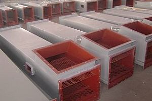
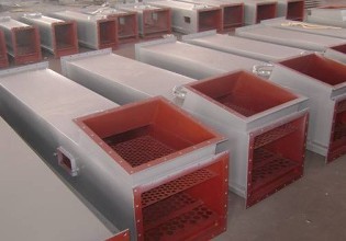
Scaffolds for Air slide conveyor systems are generally chosen to be made of 100-slot steel and H-shaped channel steel. The uppermost horizontal channel steel is 100mm from the top of the standing channel steel, and the height is preferably higher than 100mm at the bottom of the air slide metal box. The width is 610mm, and the thickness of the ground screw plate with 200mm*200mm welded at the bottom is 10mm, and the screw holes of the floor pin are drilled.
2. Bracket installation
The brackets are arranged evenly under the main channel of the air slide metal box, and the distance is 2M. The ground wire is fixed.
2. Main gate installation
Prior to the installation of the air slide metal box, the main gate must be installed in the old air slide metal box and sealed.
3. Main air slide metal box installation
1. Installation of the lower tank
Before installing the air slide metal box, open the air slide metal box first, and install the lower trough in numerical order on the bracket. The flange installation must add wool felt pad, and evenly coat the white mating flange with white latex. The screw hole is heated with an iron bar that is slightly smaller than the diameter of the mounting bolt, and perforated at the area where the hole is to be pierced. Be careful not to let the fire burn the felt when punching
2. Installation of breathable plate
a. Trim, cut the Air Slide Fabric to the required size, and block the incision with an electric iron (or a heated steel bar) to prevent it from dissipating;
b. Make a hole, heat it with an iron bar that is slightly smaller than the diameter of the mounting bolt, and pierce the area around the Air Slide Fabric that needs to be perforated. Be careful not to let the open flame burn the Air Slide Fabric when punching. If drilling with a drilling rig, use a hot iron stick to block the hole during the hole to prevent it from dissipating.
c, will be through the Air Slide Fabric tiled in the lower slot, through the bolt, surrounded by iron bars pressed, tighten the screw can be used;
d. The burrs (or flanges) should be deburred and the joints ground.
e, in order to ensure the seal, to be in the Air Slide Fabric around the lower surface of white latex
3. Installation of the upper slot
After the air-permeable panel is installed, cover the slot. Note that the white latex must be coated around the screw hole in the upper groove. The flange must be added with wool felt and coated with white latex. After the docking is complete, apply a waterproof sealant evenly around the flange.
4. Gate motor installation
1. The gate motor is an electric push rod, which is the power device of the feeding actuator.
2. Before installing the three (four) through slots, the electric push rod must be installed and the stroke limit device of the push rod must be adjusted so that the gate can be fully opened or closed.
3. Installation of the motor: First remove the two motor shaft bases installed on the motor base and install it on the motor shaft. Then, align the motor parallel to the motor base and attach the bolts.
5. Gate motor line installation
Please install according to the circuit diagram. It should be noted that when the 5th position is closed, the 6th position will be opened. When the 6th position is closed, the 5th position will be opened. In the 5th and 6th positions, one is the normally open position. Avoid stocking of the main channel and affect the service life of the air slide metal box.
6. Fan installation
The fan is installed on a well-prepared bracket. The height of the bracket is preferably no more than one meter from the air inlet of the air slide metal box. Connect the air outlet of the fan and the inlet of the air slide metal box with a hose.
7. Exhaust outlet installation
The air slide metal box exhaust vents on the air slide metal box of the discharge air slide metal box. After passing through the exhaust duct, it should enter a small cloth bag dust outlet. Its air volume is 1.5 times the required air volume, and the upper trough pressure at the air outlet is required to remain around 0.


